We have been given a task to follow a tutorial on how to create a robotic arm in 3D Studio Max.
The tutorial, we followed was a video and audio tutorial so we could see how the guy was creating it and had clear instructions on how to recreate it like he did.
At first he opened up a picture of what the final product would look like and shows us the basic structure of it before moulding it to look more like the robotic arm.
The entire robot arm is created from primitives like boxes, cones, spheres and cylinders these are fancy names of a 2D object for example a box is a square but because it has X, Y and Z, Z adds depth to the 2D object to make it 3D.
Rounding off the edges of the base
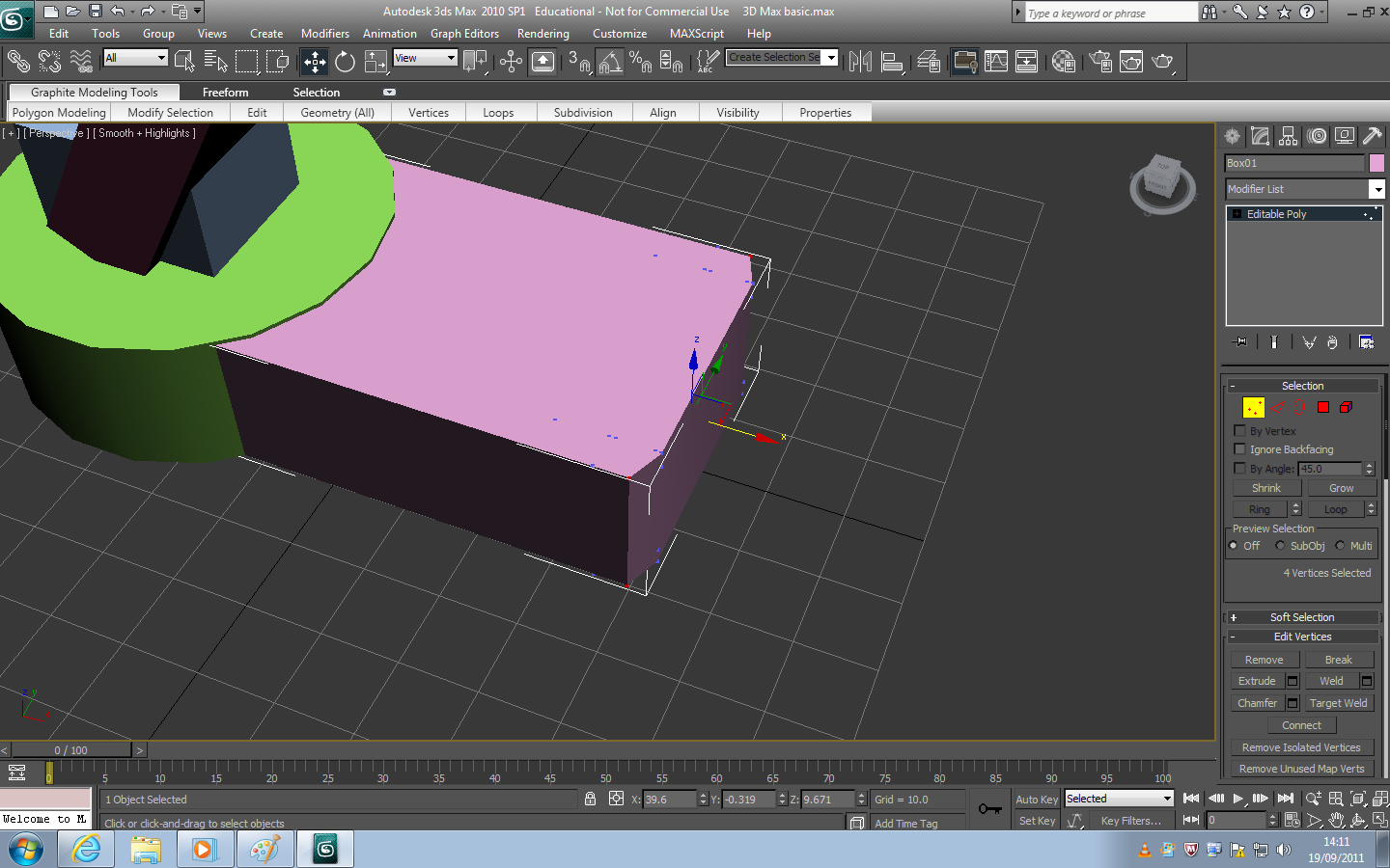
Once you have used the primitives to build the structure of the robot and made them fit together you can being to sculpt it. Firstly I took the top base and rounded off the back edge to give it a curve, to do this you must take the edges from the base and use this tool called “Ring” and “Loop” this will let you control a red line and you can place it anywhere, this is designed to stop you from rounding off the edge too far. To round the edges you select the “Vertex” tool and then press “W” which brings up a 3 way movable controller Blue for Z, Red for X and Green for Y his allows you to move it in a different axis. To get the corner you must bring the X axis in to round the edge off.

After rounding off the bottom of the base, making the small box and curved edges
After I rounded off the edge of the base and then made a smaller box on top of the base, I copied the same procedure as the base on where I made the corners round and added a chamfer which is when you round of edges to make them smooth. Once I had finished that I added in two cylinders one on top of the base and connecting to the top of the box and another on the side of the base and I made it about 1cm higher than the actual base.

Making the bottom holded and making a bolt
After I did that I added a lip on the side of the circular base that supports the arm, I also raised a part of the circle up in the middle to lift the bottom of the arm up, I changed the box at the bottom of the arm from just using the “Vertex” tool to round off the edges of the box to make it have a flat top and bottom but the sides to be curved. Once I had finished the base of the robotic arm I attached it all together and that’s why the colour of the base has a dark blue.

Made the lower arms and upper bolt
Now that I have finished the base of the arm, I created a bolt/axis that makes the arm movable but holds it into position I did this from using a sphere but cutting it in half and removing the top of it and adding in a cap to make the face of it flat instead of it being rounded off. Once I had completed one side of it the hard work was done I just had to hold Shift + Left mouse to duplicate it and once I had done that I pressed “R” and rotated it to fit on the other side. Now that the bolts/axis are completed it I started to make the bottom legs of the arm and for this I did the same procedure as the base using the “Ring” and “Loop” I used connect and made two red lines before then removing the centre of the legs and adding a cap to in the inner of both legs and once I had finished that I attached them with the rest of everything else that was complete.
NOTE: When attaching not all of the colours will match they don’t all go Dark Blue.

Making the upper body structure
Now that I have finished the base and the bottoms of the legs, I’m now working on the upper leg structure and these are made up of two of the boxes with the edges corned. For this is just used Shift + Left mouse on the same one I created before and made two copies of it because there is no need to remake them your just making more work for yourself. Now that you have two of them you need to create an instance, an instance basically makes a copy of them and whatever you do on them will edit the other one, it is good for creating something on a straight line instead of creating something and adjusting the rotation etc. Now that I had created an instance I began to edit the model on the right hand side and it will then copy it to the model of the robotic arm.

Upper body structure in progress using a instance
Once I had finished the top of the arm I made another bolt/axis and then duplicated it to the other side instead of making another, Now that the bottom and the top part of the robotic arm are complete I began to work on the claw/grabber I created another instance like it did with the top of the arm and rotated it straight so it’s easier to edit. I firstly rounded off all of the edges with the “connect” tool and then pressed “W” and brought them in, after I did that used the “chamfer” tool to create the edges round and after that I made a cylinder on the side and then duplicate it to the other side.

The claw of the robot arm
Now to finish off the rest of the robotic arm, just need to create the arms for claw these are made up of a box that has been readjusted and a cylinder and another box that has been adjusted. Once I have finished them off I just needed to make another one of them by duplicating it and mirroring it to rotate it around. I then attached it to the top part of the arm and made two small boxes to attach it onto the arm and I then removed the two instances to get the final outcome.

Robotic arm complete before textured and lit

Robotic arm has been textured
I have now textured the robotic arm; I got the textures from cgtextures.com and downloaded the ones that I wanted, after texturing the robot arm I added in lighting and a camera.

Lighting the robotic arm and adding in a camera

Final product


Wireframe
Wireframe is a visual presentation of a three dimensional object. It shows the edges and the outline of a shape once it is turned into a model of something. Wireframe visualizes the underlying design of a 3D model.


Edge – Edge tool allows you to select the edges of vertices and enables you add things like chamfers, weld, loop and connect
Border – Selects the borders to extrude and chamfer.
Polygon – Select faces of the model and you can extrude them.
Element – Selects all faces of the model
Comparing and contrasting box modelling and extrusion modelling
Box modelling is a technique used in 3D modelling it is created by modifying primitive shapes (E.G Cube, Cylinder) to create a rough draft of the final model.
Extrusion modelling is a technique where you create a 2D shape of an object or photo and you can extruded the 2D Shape into a 3D Shape by either pulling it up or down from the shapes outline.
Box modelling and Extrusion modelling are similar in a way of modelling shapes into something but with box modelling you pick the primitive you want and you can model them into your final product. With extrusion modelling your picking a 2D flat plane like a cube which is a square and you are dragging it up to make into a cube which is a 3D object.
Word check 1,079
No comments:
Post a Comment